
Choosing HMI sensor solution depends on your application's budget, form factor, and environment. Capacitive touch springs deliver flexibility for curved surfaces, while PCB copper electrodes offer a low-profile option for flat panels. Which technology provides the best cost-performance balance for your project?
Capacitive sensing reduces costs by 40-50% compared to mechanical switches. This advantage makes touch buttons attractive for modern designs. Your user experience depends on proper feedback—both LED feedback and tactile response matter. The spring approach suits metal-plate capacitive touch springs in wearables. PCB capacitive touch spring designs integrate directly into your front panel.
This guide examines key factors affecting your front panel layout and LED feedback integration. Your choice impacts every touch interaction.
Key Takeaways
-
Capacitive touch springs work best for curved surfaces and prototypes. PCB copper electrodes suit flat panels and high-volume production.
-
Both technologies cut costs by 40 to 50 percent compared to mechanical switches. They have no moving parts, so they last longer.
-
Capacitive sensing uses very little power. It draws microamps in sleep mode, which extends battery life for portable devices.
-
User experience depends on touch sensitivity and feedback. LED indicators confirm touches. Mutual capacitance handles wet hands better than self-capacitance.
-
For quick prototypes, choose springs. They allow you to change height and position without redesigning the board. For mass production, choose PCB electrodes. They reduce assembly steps and lower per-unit costs.
Capacitive Touch Springs Overview
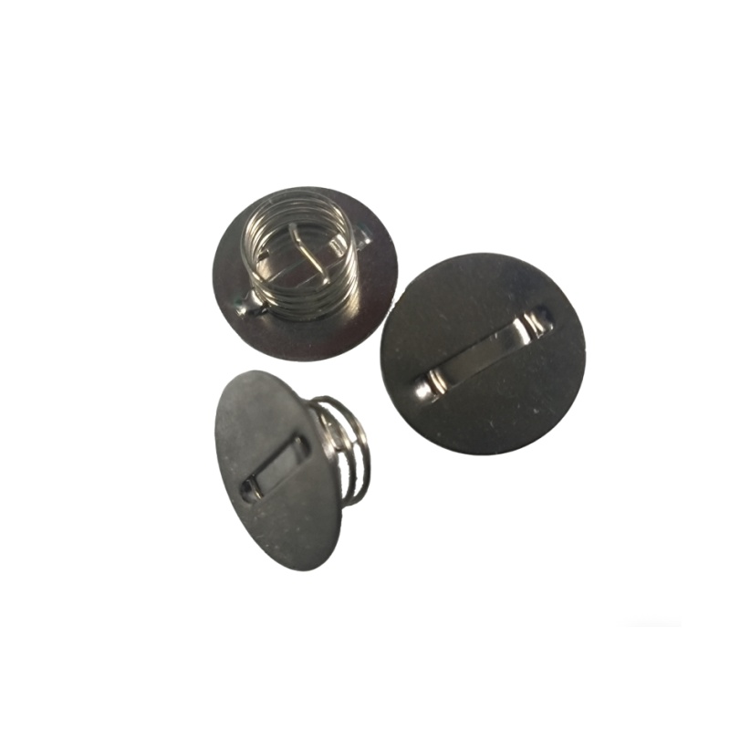
Capacitive touch springs convert a simple metal coil into a reliable sensing element. You mount the spring behind your front panel material, and it forms one electrode of a capacitor. The spring's conductive surface works with the human body to create a detectable change in capacitance. This approach gives you design freedom because the spring can compress, bend, and adapt to curved surfaces.
How Springs Enable Sensing
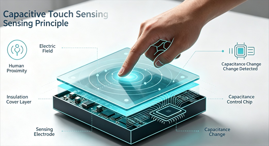
The metallic spring acts as one electrode of a capacitor. Your finger becomes the other electrode when it approaches the surface. The electric field between these electrodes changes with finger proximity. The sensor circuitry detects this change and registers it as a touch event.
When a human finger approaches or touches the sensing plate, the human body itself has a certain capacitance. The inductive capacitance formed by the finger and ground connects in parallel to the original capacitance between the sensing plate and ground. This parallel effect causes the total capacitance value to increase rapidly. The control circuit continuously detects this change, and when it exceeds a preset threshold, the circuit converts the change into an electrical signal that triggers the touch operation.
Your touch controller measures this capacitance shift continuously. The spring's geometry and material properties affect sensitivity. Metal-plate capacitive touch springs offer enhanced stability for demanding applications. You can tune the sensing range by adjusting spring height and coil density.
Pros and Cons for HMI
Capacitive touch springs excel in several application areas. The table below shows common uses and their advantages.
|
Application |
Why Preferred |
|---|---|
|
Liquid level sensing |
No moving parts, compact design, reduced cost, high reliability |
|
Tactile feedback |
Immediate confirmation of touch, improves accuracy in noisy conditions |
|
Smart keyless locks |
Eliminates physical keys, supports keypad or biometric inputs |
|
Proximity sensing |
Activates display when user approaches, improves energy efficiency |
The robustness of this technology stands out. Sealed surfaces achieve IP65, IP67, or IP68 ratings. No moving parts means no mechanical wear. Industrial-grade solutions last millions of touch cycles, while mechanical buttons may fail after hundreds of thousands of uses. Maintenance reduces to periodic surface cleaning.
Your user benefits from software-defined controls. You can change interface layouts based on operating modes without hardware changes. A single module replaces dozens of mechanical keys, simplifying assembly and reducing part costs. Touch feedback through LED feedback confirms each interaction. This combination of flexibility and durability makes capacitive touch switch designs attractive for modern HMI projects.
PCB Copper Electrodes Overview
PCB copper electrodes use etched traces on a standard circuit board as the sensing element. You integrate the electrode directly into your front panel PCB, eliminating separate mechanical parts. This approach suits flat surfaces and high-volume production.
PCB Traces and Capacitive Sensing
The copper trace forms one plate of a capacitor. Your finger acts as the other plate when it approaches the touch panel material. The touch controller measures the capacitance change and registers the touch event. This capacitive sensing method works reliably through thin overlays.
Standard fabrication produces these electrodes through a well-defined flow. The process includes inner layer fabrication, lamination, drilling, copper plating, etching, solder mask, silkscreen, and surface finish. Fine-line etching achieves 75–100 µm line/space precision for the copper electrodes. Laser drilling creates microvias for compact multi-layer architectures. Electrical testing verifies capacitance consistency and sensor performance.
Trace layout directly affects sensing quality. The table below summarizes key requirements.
|
Trace Layout Factor |
Specific Requirement |
Impact on Touch Detection |
|---|---|---|
|
Trace length |
Keep driver and sensor traces short |
Minimizes parasitic capacitance, improving signal-to-noise ratio |
|
Shielding |
Use ground traces (≥0.2 mm) around sensitive signals |
Prevents interference, stabilizing measurements |
|
Trace crossing |
Avoid crossing; prefer perpendicular crossings |
Reduces junction capacitance distortion |
|
Antenna spacing |
Maintain ≥20 mm from RF antennas |
Reduces RF interference, preserving accuracy |
Your electrode design must also account for trace width and spacing. Narrower widths increase impedance; wider widths lower it. Specify line width tolerances explicitly—10–15% for standard designs. Use symmetric stackups with adjacent ground planes to stabilize impedance. The conductive path must remain consistent across the entire electrode area.
Advantages and Limitations
PCB copper foil electrodes offer several benefits. They provide a low-profile solution that integrates directly into your front panel. Manufacturing costs drop at scale because you produce electrodes alongside the main PCB. LED feedback integrates easily with nearby traces. The sealed surface achieves high IP ratings without additional parts. This pcb copper foil approach also simplifies assembly.
However, limitations appear with non-flat surfaces. The bending radius must be carefully controlled, as bending beyond the limit can destroy the board. A sharp bend increases circuit damage risk. Design copper patterns to accommodate flexing in active bend areas. Copper imbalance can cause warpage, which may affect assembly quality. This creates poor solder joints and micro-cracks in traces.
For flat panels, this technology delivers reliable touch buttons with minimal assembly complexity. The capacitive touch switch design works well when you need consistent performance across thousands of units. Your user receives immediate feedback through LED feedback indicators. LED feedback confirms each interaction clearly. This capacitive technology excels in applications where the front panel remains rigid and flat. The conductive traces maintain stable performance throughout the product lifetime.
Key Factors for Choosing HMI Sensor Solution
Your choice between springs and PCB electrodes shapes three critical outcomes: cost per unit, power draw, and long-term reliability. Capacitive technology already delivers a 40-50% cost reduction over mechanical switches. Both sensing approaches build on this advantage, but they diverge in how they affect your bill of materials and assembly process.
Cost, Performance, and Power Efficiency
Capacitive touch switch designs eliminate moving parts entirely. You remove the mechanical actuator, the return spring, and the wear-prone contact surfaces. This simplification cuts procurement costs and reduces assembly time. The touch controller handles multiple buttons from a single chip, so you avoid per-button wiring and connectors.
Power efficiency follows the same pattern. Capacitive sensing draws current only during measurement cycles. Your system sleeps between scans, consuming microamps rather than the continuous current a mechanical switch matrix requires. For battery-powered devices, this difference extends operational life substantially.
The sensing method you choose affects performance characteristics. Self-capacitance measures each electrode against ground. This approach offers higher sensitivity and simpler design at lower cost. Mutual capacitance measures changes between intersecting electrodes. It provides true multi-touch capability, excellent noise immunity, and faster response.
Self-capacitance measures individual electrode-to-ground capacitance (higher sensitivity, simpler design), while mutual capacitance measures changes between intersecting electrodes (better for multi-touch, excellent noise immunity and responsiveness).
Your application determines which method suits your needs:
-
Self-Capacitance: Higher sensitivity, simpler design, lower cost; but limited multi-touch support (ghosting effects).
-
Mutual Capacitance: True multi-touch capability, excellent noise immunity and responsiveness; widely used in smartphones and tablets.
For single-button interfaces, self-capacitance keeps costs minimal. For complex panels with multiple simultaneous touches, mutual capacitance justifies its higher complexity.
Impact on User Experience and Durability
User experience depends on how reliably your touch buttons respond under real-world conditions. Wet hands, electromagnetic interference, and rapid successive touches all challenge sensing reliability. The table below compares two controller implementations.
|
Sensing Element |
Touch Sensitivity |
Response Time |
User Satisfaction Factors |
|---|---|---|---|
|
CTSU (Mutual Capacitance) |
Reliable operation in wet conditions; seamless operation with wet hands |
Not explicitly stated, but industrial-grade noise immunity ensures consistent performance |
Waterproofing (no unintended malfunctions), noise immunity for industrial environments |
|
CTSU2 (Self-Capacitance) |
Simplified waterproof design; better development ease |
Mutual Simultaneous Scan speeds up touch measurement via parallel processing, ensuring high responsiveness |
Medical-grade noise immunity, energy efficiency (low power consumption), support for multi-button applications |
Your front panel material and thickness directly affect touch sensitivity. Thinner overlays produce stronger capacitance signals. Thicker materials require higher sensitivity settings, which may reduce noise immunity. Metal-plate capacitive touch springs offer enhanced stability when you need consistent performance through thicker panels.
Durability differences emerge over time. Springs maintain their shape through millions of compressions. PCB electrodes have no moving parts to wear. Both approaches achieve IP65 or higher sealing. The real durability question concerns your enclosure. A curved surface that flexes during use favors springs. A rigid flat panel favors PCB electrodes.
LED feedback integration affects both user experience and manufacturing cost. Springs require separate LED placement near the coil. PCB copper electrodes allow LED feedback traces routed directly beside the sensing element. This integration reduces assembly steps and improves visual alignment between the touch target and the indicator.
Your touch controller choice also matters. A controller with built-in noise filtering reduces false triggers. This reliability improvement directly enhances user satisfaction. Users notice when buttons respond consistently. They abandon devices that miss touches or activate unexpectedly.
For your choosing hmi sensor solution decision, weigh these factors against your production volume. Low-volume prototypes benefit from spring flexibility. High-volume flat panels benefit from PCB integration. A pcb capacitive touch spring design bridges both worlds when you need spring mechanics with PCB manufacturing efficiency.
The final consideration involves your development timeline. Springs allow rapid iteration without PCB redesign. PCB electrodes require layout changes for each adjustment. Your team's familiarity with each technology affects your time-to-market. Choose the approach your engineers can implement fastest while meeting your performance targets.
Choosing HMI Sensor Solution: Application Scenarios
Your product's physical shape and production volume determine which technology fits best. Goodkey manufactures both capacitive touch springs and PCB copper electrodes, so you can evaluate each option against your specific requirements. The following guidance helps you match your application to the right sensing approach.
When to Use Capacitive Touch Springs
Capacitive touch springs suit products with curved enclosures or irregular surfaces. The spring compresses behind the front panel material, adapting to contours that rigid PCB electrodes cannot follow. This flexibility makes springs the preferred choice for wearables, headphones, and other compact devices where space is tight.
The list of suitable applications spans many industries:
-
Smartphones and tablets
-
Touch-sensitive control panels and displays
-
Laptops and computers
-
Consumer electronics
-
Automotive interfaces
-
Gaming consoles
-
Home automation systems
-
Industrial controls
-
Medical devices
-
Public spaces
A pcb capacitive touch spring design combines the spring's mechanical flexibility with standard PCB manufacturing. You mount the spring directly onto the board, creating a reliable sensing element without complex assembly. This approach works well for prototypes because you can adjust spring height and position without redesigning the entire board.
Industrial control panels benefit from spring-based sensing when the enclosure has a curved or textured surface. The spring maintains consistent contact with the front panel, ensuring reliable touch detection across the entire button area. Metal-plate capacitive touch springs provide enhanced stability for these demanding environments.
For wearables, the spring's ability to conform to curved surfaces proves essential. Your device fits comfortably against the user's wrist or head while maintaining accurate touch detection. The spring also provides mechanical cushioning, absorbing minor impacts without damaging the sensing element.
When to Use PCB Copper Electrodes
PCB copper electrodes excel in high-volume products with flat surfaces. You integrate the electrode directly into the front panel PCB, eliminating separate mechanical parts. This integration reduces assembly steps and lowers per-unit costs at scale.
Flexible PCBs for consumer electronics demonstrate this advantage clearly. Laptops and smartphones use copper foils with controlled matte side characteristics. These boards withstand repeated flexing over many cycles at a tight bend radius. They maintain minimal surface roughness to avoid fatigue cracks. This durability makes them ideal for connections between laptop screens and keyboards that fold thousands of times.
Hard drives also rely on flexible PCBs for high-speed data transfer and heat resistance. Engine management units in vehicles use the same technology for reliable operation in harsh conditions. These examples show how PCB copper electrodes deliver consistent performance in demanding applications.
Your touch buttons on a flat front panel benefit from the low-profile nature of PCB electrodes. The sensing element sits flush with the board surface, requiring no additional clearance. LED feedback traces route directly beside the electrode, improving visual alignment between the touch target and the indicator. This integration enhances user experience through immediate visual confirmation.
For mass production, PCB electrodes offer clear advantages. You produce the sensing elements alongside the main circuit board, reducing procurement complexity. The touch controller integrates seamlessly with the electrode layout. Your assembly line handles fewer parts, cutting labor costs and improving quality control.
The choice between springs and PCB electrodes ultimately depends on your product's form factor and production volume. Curved surfaces and prototypes favor springs. Flat panels and high-volume manufacturing favor PCB electrodes. Goodkey's engineering team can help you evaluate both options for your specific application.
Your choosing hmi sensor solution decision depends on your product's shape and volume. Capacitive touch springs excel in curved enclosures with robust mechanical integration. PCB copper electrodes suit low-profile, high-volume products with flat surfaces. Your touch controller choice affects sensing performance.
The capacitive approach delivers reliable touch detection. Your user experience depends on proper feedback. LED feedback confirms each touch interaction clearly. Design your front panel around your chosen technology. Capacitance changes trigger the touch controller response. Your user receives immediate feedback through LED feedback indicators. The touch button design requires careful front panel planning. LED feedback integration improves the user touch experience. Each touch event requires consistent feedback from your front panel design. Touch sensitivity affects overall performance.
Your touch interface must respond reliably. Every touch counts in user satisfaction. For prototypes or curved enclosures, start with capacitive springs. For mass-produced flat panels, favor PCB electrodes. Consult Goodkey to test both solutions.
FAQ
How do I decide between springs and PCB electrodes for my product?
Examine your enclosure shape first. Curved or irregular surfaces favor springs because they compress and adapt to contours. Flat panels suit PCB electrodes. Then consider production volume. Low-volume prototypes benefit from spring flexibility. High-volume manufacturing favors PCB integration for lower per-unit costs.
Can both technologies work with wet hands or in humid environments?
Yes. Both approaches support waterproof designs when you seal the front panel properly. Mutual capacitance controllers handle wet conditions reliably. Self-capacitance controllers offer simplified waterproofing with easier development. Your choice of controller matters more than the sensing element itself for moisture performance.
What maintenance do these touch solutions require?
Neither technology has moving parts, so maintenance stays minimal. You clean the surface periodically to remove dirt and oil buildup. Industrial-grade solutions last millions of touch cycles without degradation. Mechanical buttons may fail after hundreds of thousands of uses, making both capacitive options more durable.
How does LED feedback integration differ between the two options?
PCB electrodes allow you to route LED traces directly beside the sensing element. This integration improves visual alignment between the touch target and indicator. Springs require separate LED placement near the coil. For a pcb capacitive touch spring design, you mount the spring on the board and position LEDs nearby during layout.
Which option works better for prototypes?
Springs win for prototyping. You adjust spring height and position without redesigning the entire board. This rapid iteration shortens your development timeline. PCB electrodes require layout changes for each adjustment. Metal-plate capacitive touch springs provide enhanced stability when you need consistent performance through thicker panels during testing.